
Sections
Using glass components in hazardous chemical service introduces risks that can lead to mechanical failure and loss of containment. Design, operation, and maintenance practices are critical in managing this risk.
Sight glasses, liquid level gauges, and sight flow indicators are critical equipment used in chemical, pharmaceutical, refinery, and wastewater treatment plants. Sight glasses provide a means to obtain visual insight into the operating conditions of reactors, pressure vessels, tanks, fired equipment, heaters, and boilers. Level gauges allow for level measurement, and sight flow indicators provide an indication of flow in pipes. Like flexible hoses, glass elements are considered weak components that are susceptible to random failures. While the inherently safer solution is to eliminate glass components, this may not always be practical, particularly in specialty chemical manufacturing. This creates unique process safety challenges. This article explores process risk management methodologies, including inherently safer designs to manage glass in hazardous service.
Historically, many glass components are installed without consideration for maximum operating temperature, pressure, and material of construction. Glass can be subjected to thermal shock, corrosion, or physical impact during operation, which may lead to failure and loss of primary containment. If the chemicals involved are highly hazardous, loss of containment may result in a fire, an explosion, and/or a toxic release. Consideration of the design pressure rating alone is not sufficient to assume suitability for service. Even if the services are relatively nonhazardous, personnel in the vicinity can be subject to the consequences of direct projectile impact and chemical exposure. The principles of loss prevention direct us to protect the weakest points of a system, but glass is often installed without adequate analysis of the consequences of failure.
Selecting glass in hazardous service
Proper selection of glass components follows common principles: compliance with all codes and standards, safety and environmental requirements, performance criteria, good engineering practices, and appropriate materials of construction. In some cases, glass components are installed as a convenience rather than out of necessity. This has led to several loss of containment incidents across many industries, resulting in undesired consequences.
Glass materials. The three most common glass materials are soda-lime, borosilicate, and quartz:
- Soda-lime glass has been used for thousands of years and used to be the most frequently installed type of glass for process facilities due to its low cost (1). However, it also has a low maximum operating temperature and is highly susceptible to degradation by water or aqueous solutions under high temperature and/or alkaline conditions depending on the concentration (2).
- Borosilicate glass is the most commonly used glass type today and is offered in both tempered and annealed forms. It is resistant to most chemicals but is still susceptible to caustic and high-temperature water or aqueous solutions. Borosilicate has a wider operating temperature range and greater strength than soda-lime glass (Figure 1) (2).
- Quartz glass has the highest operating temperature range, up to 980°C (1,800°F) (2). However, quartz is also the most fragile of all glasses. Still, quartz finds use in some specialized pharmaceutical and high-temperature equipment applications.

▲Figure 1. High-temperature water and alkalinity chemically degrade glass components, although borosilicate glass has greater resistance than soda-lime glass. When considering glass components for use in a process, it is crucial to consider all operating parameters to which a component could be exposed. Source: Data from (2).
For most applications involving highly hazardous chemicals, borosilicate glass provides the widest available operating range in conjunction with good chemical resistance and durability.
Types of glass. Borosilicate glass is available in three forms — annealed, tempered, and fused. Each has specific areas of application:
- Annealed glass is the most basic form available on the market. This glass type forms many sharp, jagged pieces upon catastrophic failure. Annealed glass may be selected when strength and safety are not significant considerations, making this a poor choice for use in highly hazardous chemical services.
- Tempered glass is manufactured such that the outer surfaces are in compression, and the inner glass is in tension (2, 3). The compression gives the glass greater strength, making it often two to three times stronger than annealed glass (2, 3). Upon catastrophic failure, tempered glass breaks into larger chunks, making it a better choice for industrial applications.
- Fused glass is available for modern sight glasses. To create fused glass, molten glass is poured inside a metal ring, heated to high temperature to form a chemical bond between the glass and metal, and then cooled (2). During cooling, the glass cools faster than the outer metal ring, putting the glass into compression. Fused glass is capable of very high strength, which is more resistant to failure. During installation, the bolt loads are established on the metal ring, not on the glass (4). Fused glass is an excellent choice for sight glass applications, due to its strength and wide operating range.
Glass components. Several different types of glass equipment are used in chemical process facilities. Figure 2 illustrates each type of glass component:
- sight glass. A flat glass, usually attached to a top nozzle on a reactor that allows visual verification of agitator operation, proper fill level, or completion of a batch transfer.
- bullseye flow glass. A piping system component with tempered flat glass that allows the user to see the flow of material through the piping. Flow indicators may have flappers or rotors to aid in assessing the flow efficiency. A bullseye flow glass is normally threaded or flanged into a port at the level at which the liquid is maintained during normal operation. It has a glass center material to allow viewing of the liquid.
- tubular level glass. A long tube of glass (usually borosilicate for increased heat and chemical resistance) sealed with fittings or flanges at each end. Some brands use polytetrafluoroethylene (PTFE) inserts so that all wetted parts are acid-resistant. Tubular level gauges usually have rods or angle iron running the length of the glass tube to reduce the lateral, compressive, and tensile forces on the glass. Tubular glass components are extremely vulnerable to torsional and bending stress failure.
- tubular flow glass. A glass tube similar to the tubular level glass except shorter and larger in diameter. Tubular flow glasses have been used in different chemical applications. However, the surface area of exposed glass is so large that breakage can quickly result in a significant loss of containment. For this reason, tubular flow glasses are not recommended in hazardous chemical service.
- armored level glass. A glass gauge used to visually observe the liquid level of a process fluid and is reinforced by steel tubing or a chamber machined from bars, steel covers, tempered glass, steel bolts and nuts. Armored glass level gauges and specially designed vessel surface-mounted sight glasses have been shown to have lower risk of failure than tubular level glasses (5).
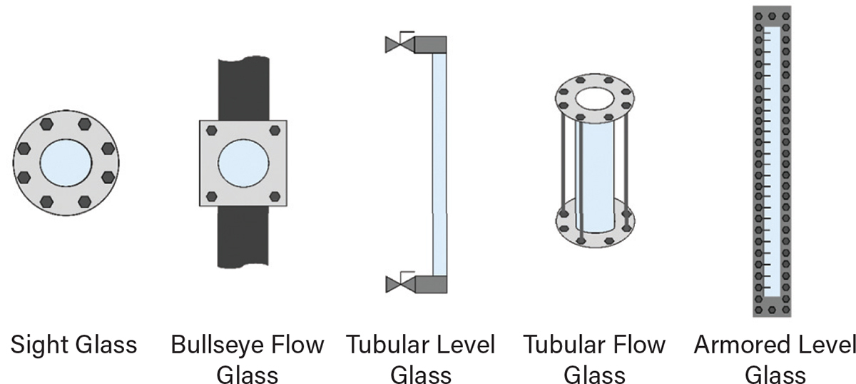
▲Figure 2. Glass components allow operators to monitor fluid level, flow, or mixing. However, each type of glass element has specific mechanical failure modes and corresponding risk mitigation measures.
Standards relevant to particular applications. While there are not many codes, standards, or certifications relevant to glass components, some are available and should be considered when selecting a glass component for a specific application. These include (2):
- DIN 7079 for fused sight glasses
- DIN 7080 for borosilicate glass quality
- ASME Bioprocessing Equipment (BPE) for components used in the biopharmaceutical industry
- U.S. Pharmacopeia (USP) Type I, II, III, and NP for pharmaceutical applications
- FM Global approved components — these may be relevant to a facility’s property insurance and loss prevention program.
Design characteristics
Proper engineering design and selection of the glass component is the first layer of protection in preventing significant harm to people, the environment, or company assets in the event of a catastrophic glass failure. Thus, the importance of the design of the glass component cannot be overstated.
Pressure rating. Pressure rating is one of the most underappreciated aspects of glass component selection and continuous use. The design pressure selected should be higher than the normal operating pressure of the system. All potential overpressure contingencies should also be accounted for — the glass component should not become the equipment or piping’s pressure relief device. The design should account for potential overpressure from all scenarios as described in the American Petroleum Institute (API) Standard 521 or other local standard (6).
Choosing the initial pressure rating upfront is important, but maintaining the pressure rating of the component during its operational life is equally important. The pressure rating of a glass component is a function of its thickness, diameter, and allowable stress, as shown in the following equation (2):

where P is the pressure rating of the glass component (psi), σ is the allowable stress for the type of glass (psi), t is the glass thickness (in.), and du is the unsupported glass diameter (in.). The pressure rating of a glass component varies linearly with the allowable stress and the square of the material thickness.
For new and like-new glass, the design pressure rating can be determined from these parameters. However, once a glass component becomes chipped, scratched, or cracked, the allowable stress becomes indeterminate due to the random, non-uniform nature of the damage effects. Hence, the pressure rating also becomes indeterminate. For this reason, properly maintaining the glass and protecting it against damage is paramount to the continued safe operation of the glass component. Recommendations for properly maintaining glass component integrity are discussed in this article. Glass that no longer has a determinable pressure rating should be immediately taken out of service.
Material compatibility. Material compatibility is another critical specification. Much like specifying the proper design pressure rating, the material compatibility must consider all anticipated operating conditions, including cleanouts or preparation for maintenance.
The most commonly overlooked material compatibilities that contribute to catastrophic glass failure involve caustic or alkaline materials and high temperature (>150°C) water. Glass is chemically attacked by caustic and high-temperature water, which degrades the Si-O bond. This weakens and erodes the glass. The chemical degradation of glass by caustic or hot water can be measured in grams, not milligrams, and occurs in a matter of weeks, not months. For caustic or high-temperature water service, quartz, sapphire, or PTFE shields applied to the wetted side of the glass component are required (7).
Certain acidic conditions can also be corrosive to glass. Hydrofluoric acid (HF) is used industrially to chemically etch glass. Use of glass components in HF service is not a good choice.
In addition to chemical degradation, glass components are also subject to erosive degradation by contact with abrasive media. For example, glass exposed to slurries or other abrasive conditions will lose thickness and integrity, and hence its pressure and temperature rating will decrease as erosion proceeds. If internal shields are not an option due to other material compatibility considerations, glass in these services would need to be frequently replaced.
Gasket selection. Proper selection of gaskets for use with glass components involves consideration of both material compatibility as well as sealing stress. Gaskets must be selected with a proper thickness and sealing stress for the application. An inadequate gasket or a gasket that has been reused can induce bending stress on the glass, increasing its likelihood of failure.
Temperature. Temperature specification must account for all anticipated operating conditions, including normal operation, foreseeable contingencies, and alternate operating modes such as cleanouts, non-routine operations, or preparation for maintenance.
Failure modes
Failures of level gauges, flow glasses, and sight glasses have caused many serious incidents across the chemical and petroleum industries. For example, a release of ethylene and subsequent explosion that destroyed a plant may have been caused by a glass component failure (8). Incident causes range from improper maintenance, inappropriate material of construction, improper operation, thermal cycling, human error, and improper design. Several incidents involving glass in hazardous service are described in a companion paper (9).
Mechanical failure. Mechanical failure is the resulting consequence when exerted stress exceeds the strength of a material. Glass can be subjected to compressive, tensional, torsional, and bending stresses, as well as environmental stresses such as thermal shock, chemical attack, and physical abrasion. Glass is amazingly strong in compressional stress but extremely weak when other stress modes are applied. Therefore, any exerted stress other than compression makes glass extremely vulnerable to catastrophic failure, especially under torsional or bending stresses.
Glass is considered a brittle material with little or no “plasticity” response, so it cannot stretch and bend by plastic deformation like steel and other materials. When glass fails, it can do so suddenly and catastrophically with a crack velocity of around 5,000 ft/sec, as first reported in 1939 (10) and recently confirmed at 4,800 ft/sec in 2018 (11). Proper glass specification (required strength), installation (stress minimization), and maintenance (lifecycle mechanical integrity) are key to minimizing potential glass failure hazard concerns.
Corrosion. Glass can be subject to chemical corrosion, with soda-lime glass being the least resistant. Water attacks soda-lime glass at a far more aggressive rate than borosilicate glass.
Wetted glass shielding materials such as mica, fluorinated ethylene propylene (FEP), or polychlorotrifluoroethylene (PCTFE, e.g., Kel-F) used to protect the glass from harsh chemical attacks can be applied. However, these materials are not as transparent as glass and may negatively affect the viewing efficiency through the glass. Corrosive chemicals can also attack the metal support structures around glass equipment, such as flanges, fusing rings, and window supports. In these instances, inert materials may be used to insulate the metal components from aggressive fluids, typically with a PTFE sealing surface around all wetted surfaces. This approach eliminates the need for expensive, exotic corrosion-resistant metal components. However, aggressive process chemicals could potentially permeate the inert shield over time and allow corrosion at the underlying metal substrate, ultimately leading to component failure. Routine inspection of the shielded metal components is highly recommended for this reason.
Erosion and abrasion. Glass can be subject to chemical erosion and abrasion, the physical degradation of surfaces by flowing media contact. High-pressure fluids at high flow velocities, especially in pipe bends, tees, and Y’s, can erode glass and steel components at an alarming rate. Abrasive media at accelerated flowrates or long-term flowing service can erode/abrade glass to the point of dangerous thinning, which leads to catastrophic failure and loss of containment. These potential erosion/abrasion failure modes add credence to routine mechanical integrity inspections to identify and address areas of concern.
Pressure cycling. Non-fused sight glass discs are vulnerable to pressure cycling effects, such as rotational periods of cyclic hot/cold and pressure/vacuum service; similar cycling failures have been observed in rupture discs. Fatigue stresses caused by such cycling accumulate, which eventually causes the glass component to fail by fatigue. Fused ring sight glasses do not suffer this failure potential due to the robust design, which places the glass in intense compression and the steel fusing ring in tension, making the glass more resistant to cycling.
Pipe stresses. Mechanical consideration — including alignment and vibration concerns — should be given to any piping design that includes glass components. Bending and torsional stresses can be induced by mating flanges not being perfectly aligned, which is never 100% certain in many applications. Imperfect alignment combined with piping vibration can lead to mechanical glass failure. For this reason, long tubular glass components are not recommended due to the high potential for stress-induced failure. If these devices are used, review the companion paper for additional considerations (9). Glass components that are mechanically aligned without induced torsional/bending stresses can still be subject to significant pressure pulse forces from hydraulic hammer. Assess this glass failure potential, and, if necessary, actively pursue viable options to eliminate the vulnerable glass component.
Thermal shock. Glass can be subject to thermal shock induced by rapidly changing temperature conditions. Some types of glass are more vulnerable to thermal shock based on thermal expansion, thermal conductivity, and the overall “toughness” of the glass. Thermal shock may occur during washdown activities when hot process vessels are subject to exterior cold-water contact. Thermal shock can occur inside a vessel during startup operations when hot or cold materials enter a vessel. Thermal shock can also occur when a hot or cold vessel is subjected to an instantaneous significant jacket temperature differential, usually because of an automated sequence change following a discrete operational step.
Tempered borosilicate glass should generally be specified when thermal shock hazards are recognized. Borosilicate glass has a lower thermal expansion coefficient than soda-lime glass leading to borosilicate being more tolerant to temperature deviations. Fused quartz glass offers an even higher tolerance to temperature deviations with the tradeoff of a higher glass component cost.
Dropped objects and impact. Sight glasses are too often used as convenient locations to temporarily place wrenches, studs and bolts, tube fittings, and other items that are suited to more appropriate storage locations. Glass equipment, especially sight glasses, are vulnerable to scratch damage by abrading objects, which can produce potential points of failure. An unprotected sight glass is also prone to impact by falling objects above. Damage caused by impact renders the value of the allowable stress for the glass material indeterminate, which leads to an unknown pressure rating of the glass window. Some facility site best practice policies require proactive protective shielding of glass components. Polycarbonate components are a good approach for this type of failure mitigation. A possible exception to the above guidelines may apply to fused sight glasses. The robust design of fused glass provides some resistance to damage by mechanical impact.
Maintenance practices
Glass maintenance and inspection guidelines tend to converge on several common themes. Standard condensed recommendations include (2, 12):
- Utilize proper bolt-up installation procedures. First, use the proper tool (torque wrench) and technique to apply tightening pressure. Above all, never attempt to tighten glass equipment under pressure/temperature operating conditions.
- Clean glass equipment using appropriate commercial cleaning agents. Never use abrasive cleaning pads or agents, wire brushes, or mechanical scraping instruments to clean glass. Do not attempt to clean a glass component while it is under pressure/temperature operating conditions. Glass with a cloudy or roughened surface after cleaning is an indication of chemical corrosion and the glass component should be replaced.
- Glass should be routinely inspected for visual damage. The three most common action steps are: replace glass with any obvious visual cracks, dings, or scratches; inspect the glass for any shiny, glistening, crescent, or star-shaped artifacts while shining a bright, concentrated light source at a 45-deg. angle to the glass surface (the glass should be considered for replacement if significant artifacts are observed); and glass with any cracks or scratches that can be detected by running a fingernail across the surface should be replaced. Also, any metal fusion ring or connection flanges should be inspected for evidence of metal corrosion, and the glass component or flange support should be replaced as necessary.
- Never reuse glass discs, panes, and gaskets due to the damaging stresses created during initial installation and use. The exception is metal-ring fused sight glass windows. The design of fused glass windows puts the sealing stress on the metal ring, not the glass. Therefore, fused-glass sight windows can be returned to service after removal.
- Use quality replacement glass components. Never install glass items that are chipped, cracked, scratched, or otherwise damaged. Pre-verify the flatness of seating surfaces and do not install warped components. Flanges should be rigid and meet the in-specification thickness for the pressure design, including bolt circle requirement for adequate torque force distribution. Gaskets should be new, clean, of proper specified thickness and diameter, and should be concentrically centered. The glass should not be allowed to contact any metal surface during installation.
Inspection and replacement intervals. Glass vendors should be consulted for appropriate inspection and replacement intervals based on anticipated chemical service and operating conditions. The vendors should also be consulted if the chemical service and process conditions significantly change. Harsh chemical service applications require shorter glass component replacement intervals.
Risk mitigation for glass in hazardous service
Process safety information. Each facility should establish detailed process safety information for all glass in hazardous service to support proper risk assessment and evaluation of mitigation options. The following is a list of process safety information that should be compiled:
- equipment/instrumentation identification number
- type of glass component
- pressure and temperature rating
- material of construction
- gasket material and thickness (where applicable)
- date of installation
- chemical service and classification
- inspection schedule
- worst expected consequence of failure (from the risk assessment).
All glass components require proper specification, installation, and maintenance practices, as described previously in this article. The following recommendations offer practical guidance for specific passive and active mitigations for sight glasses, flow glasses, and level glasses to reduce the risk of failure associated with these components in hazardous service.
Sight glasses. Mitigating the risk associated with the use of sight glasses in hazardous service can be accomplished by the following recommended practices:
- Choose a fused glass component whenever practical. Fused glass is much stronger than tempered or annealed glass and more resistant to chips, scratches, and cracks that result from external impact. Fused glass is also not nearly as affected by pressure cycling and is more tolerant to thermal shock within reasonable limits.
- If a fused glass component is not practical, consider using an external polycarbonate shield over the top of the glass flange to protect the glass. An example of this type of installation is shown in Figure 3. These have the advantage of being inexpensive and can often be fabricated in the facility’s maintenance shop with simple tools. When the outer polycarbonate shield becomes scratched, or its light transmission is degraded, replace the polycarbonate shield. It is far more economical to replace a small polycarbonate shield than a several hundred- or thousand-dollar sight glass. The shield also provides protection against glass failure from pressure cycling since single-paned tempered glass is not as resistant to pressure cycling as fused glass. For protection against air ingress due to failure under vacuum, an O-ring can be installed in a half-round groove cut into the polycarbonate shield between the shield and flange face.
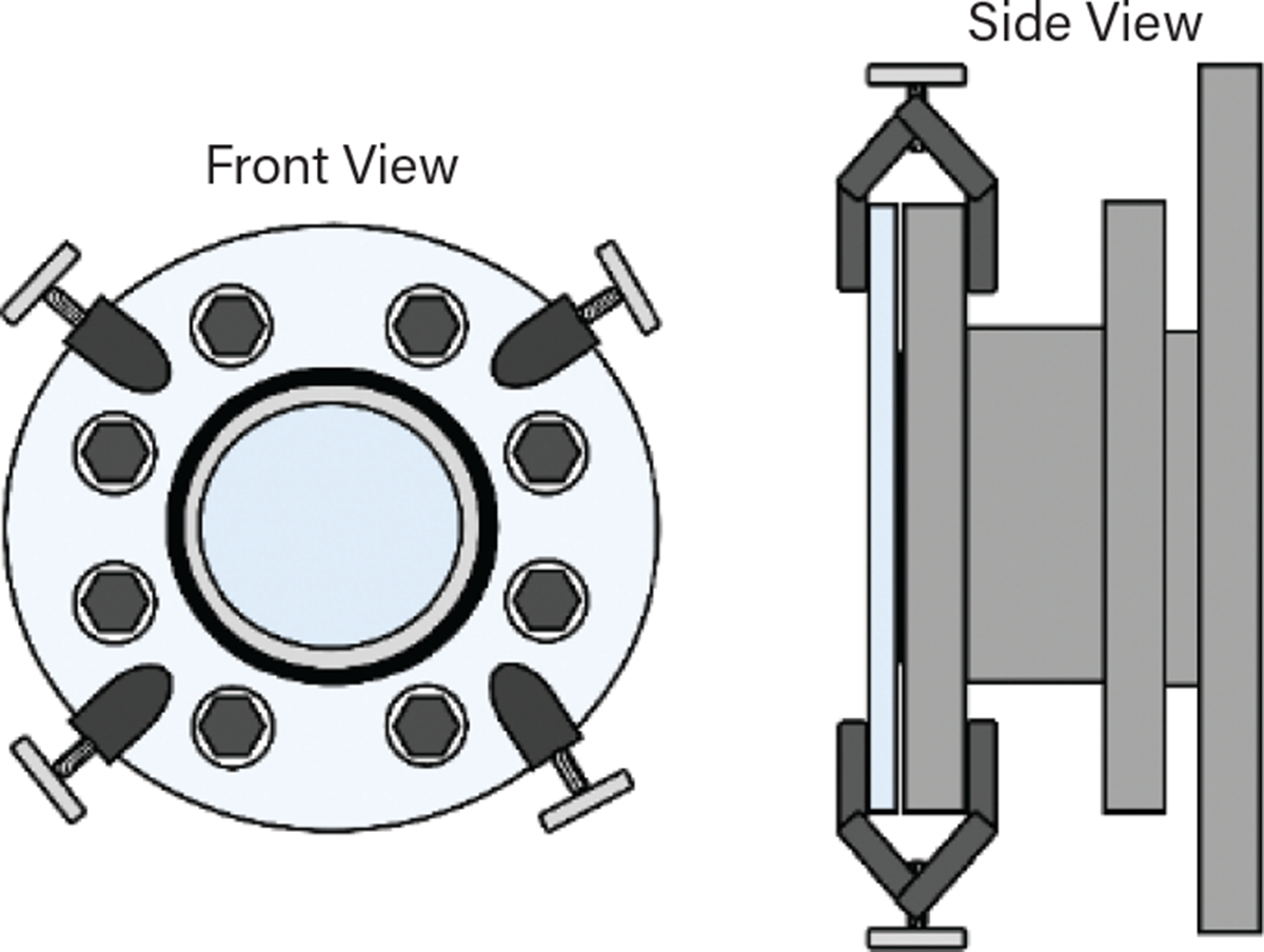
▲Figure 3. Covering a sight glass with a polycarbonate shield is one way of reducing the likelihood of mechanical failure and loss of containment in an operation. Polycarbonate shields are flame- and impact-resistant, and they deflect blasts radially, helping protect personnel.
Providing an impact shielding material between the glass and external operations and maintenance activities makes sense to protect the glass from people and people from the glass. Polycarbonate polymer is both impact- and flame-resistant. For vessels utilizing flammable or toxic hydrocarbons or pyrophoric materials, adding a polycarbonate shield could significantly mitigate the consequences in a glass failure scenario. In this case, the polymer shield would act to radially deflect a fireball should immediate ignition occur following a sight glass failure. In contrast, without the shield, the impacted personnel could potentially receive a fatal blunt force impact or fireball blast to the head.
The use of external shields to protect against catastrophic failure of glass components dates back over 120 years. A British patent from 1896 describes an external shield to protect water level gauges on steam locomotives (13).
One note of caution — be sure to use polycarbonate and not acrylic shielding. Polycarbonate is inherently impact-resistant and flame-resistant, while acrylic is not.
- If neither a fused glass nor an external shield is practical, specify a double-paned glass. A double-paned glass as manufactured may have its outer pane as either glass or polycarbonate. The addition of the second pane gives an extra layer of protection such that if one pane is compromised, the second is fully rated for the design conditions. Double-paned glass components may have better optical transmission than an external polycarbonate shield. However, double-paned glass is still susceptible to pressure cycling fatigue, chemical corrosion, and thermal shock. Once either of the glass panes is damaged or degraded, the entire component must be replaced.
Flow glasses. Flow glasses are susceptible to impact from tools, ends of hoses, and other process equipment being moved around the area. Because they are in-line devices, they are also more prone to failure from erosion/abrasion than sight glasses. Operating conditions can subject them to thermal shock and pressure cycling fatigue.
Mitigating the risk associated with the use of flow glasses in hazardous service can be accomplished by the following recommended practices:
- Use a bullseye-type flow glass as much as practical to minimize the amount of glass surface exposed to process fluids and available for external impact. Bullseye-type flow glasses are also easier to install and align and are not subject to the bending moments that can damage tubular flow glasses.
- Use an external polycarbonate shield over the outer face of the glass flanges to protect the glass. An example of this type of installation is shown in Figure 4 for a bullseye-type flow glass. External polycarbonate shields are commercially available when tubular flow glasses must be used.
- If an external shield is impractical, consider a dual-paned bullseye flow glass.
- Flow glasses used in erosive/abrasive services should be placed on a robust inspection and frequent replacement schedule to address pending glass degradation before a catastrophic failure can occur.
- As an active mitigation step, flow glasses should be fitted with actuated valves upstream of the flow glass, which can be closed remotely or automatically in the event of loss of containment to reduce the amount of material that can be released.
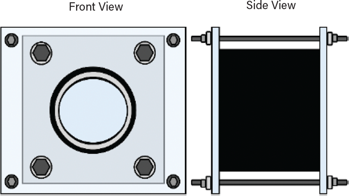
▲Figure 4. Polycarbonate shields also decrease the likelihood of failure when used over a bullseye flow glass. For systems that include bullseye flow glasses, fitted polycarbonate shields are easily constructed.
Level glasses. Level glasses are subject to impact from vehicles and other plant traffic, as they often “stick out” from the adjacent vessel or tank. They are also susceptible to pipe stresses, thermal shock, and chemical corrosion.
Mitigating the risk associated with the use of level glasses in hazardous service can be accomplished by the following recommended practices:
- Where possible, use a magnetic level gauge instead of a tubular or armored level glass. Magnetic gauges eliminate the hazards of glass; this is an example of applying the principles of inherently safer design (ISD). A magnetic level indicator is typically made of a float containing a magnet that trails the liquid level inside a chamber. The magnet inside the float indicates the level by relating with the magnets on the outside of the chamber. The measuring chamber can be constructed of metal, which has a wider operating condition range than glass level gauges.
- When magnetic level gauges are not practical, an armored level glass should be specified. Armored level glasses have far less exposed glass area than tubular level glasses, minimizing the area that can be externally impacted. Armored level glasses also greatly reduce the likelihood of failure due to pipe stresses, as the installation load is taken primarily by the metal structure and minimal glass is in contact with the process fluid.
- When level glasses are used, they should be fitted with ball check cocks, which prevent a massive process fluid release in the event of glass breakage. Unfortunately, the balls are sometimes removed by personnel who do not understand their purpose. The hand valves must be fully opened, or the balls cannot operate (8).
- In an example configuration to manage the risk using administrative controls, the glass level gauge can be isolated during normal operation by keeping the isolation valve between the level gauge and the vessel normally closed; the isolation valve is opened only to take a measurement.
- An excess flow valve can be installed on a glass level gauge between the isolation valve and the pressure vessel or tank. Excess flow valves are open in normal operation but will close when the flowrate exceeds design flowrates to reduce the amount of hazardous chemical that is released. However, careful consideration must be made — excess flow valves respond only to large outflows, such as catastrophic ruptures, but may not close for small leaks. Additionally, excess flow valves cannot operate if the line has restrictions or blockages. The presence of elbows, block valves, and other piping components may create enough pressure drop to render the excess flow valve inoperable. Alternatively, for some systems, a restrictive orifice can be installed to limit the flow of liquid or gas upon glass failure.
In closing
The inherently safer choice is always to remove any glass that is not absolutely necessary for operation. If glass components must be used, they should be properly selected and specified, accounting for the range of expected operating conditions and contingencies. Once installed, components must be adequately maintained, protected from all possible failure modes, and kept on an adequate maintenance and inspection protocol. This article has presented recommended mitigations to protect the glass and maintain its operating integrity.
We hope that the guidance and recommendations presented here will be of value to other process safety practitioners and will lead to a reduction in incidents associated with glass components across the chemical process industries (CPI).
*This article is an abbreviated version of the Process Safety Progress article “Only the best is good enough: Managing the risks of glass in hazardous service,” 41 (4), pp. 687–701, https://doi.org/10.1002/prs.12397.
Literature Cited
- L.J. Star, Inc., “Sight Flow Indicators Handbook,” Twinsburg, OH, https://www.ljstar.com/wp-content/uploads/2019/11/sight-flow-indicators-handbook-1.pdf (2012).
- L.J. Star, Inc., “Chemical and Pharmaceutical Sight Glass Application Handbook,” Twinsburg, OH, https://www.ljstar.com/wp-content/uploads/2019/11/chemical-pharmaceutical-handbook.pdf (2007).
- Swift Glass, “Understanding the Difference between Annealed Glass and Tempered Glass,” Elmira, NY, https://info.swiftglass.com/lp-understanding-difference-between-annealed-glass-and-tempered-glass (accessed March 2, 2023).
- Canty Process Technology, “ANSI / DIN Fuseview Sight Glass,” JM Canty, Inc., Buffalo, NY, www.jmcanty.com/product/ansi-din-fuseview-sight-glass (accessed Feb. 28, 2023).
- Center for Chemical Process Safety, “Practical Approach to Hazard Identification for Operations and Maintenance Workers,” CCPS, American Institute of Chemical Engineers, New York, NY (June 2010).
- American Petroleum Institute, “API Standard 521, Pressure-Relieving and Depressuring Systems,” 7th Ed., API, Washington, DC (June 2020).
- Canty Process Technology, “Chemical Industry,” JM Canty, Inc., Buffalo, NY, http://www.jmcanty.com/wp-content/uploads/TA11500-1028.pdf (accessed Feb. 28, 2023).
- Kletz, T., and P. Amyotte, “What Went Wrong? Case Histories of Process Plant Disasters and How They Could Have Been Avoided,” 6th ed., Elsevier/IChemE, London, U.K. (June 2019).
- Ashley, N., et al., “Only the Best is Good Enough: Managing the Risks of Glass in Hazardous Service,” Process Safety Progress, 41 (4), pp. 687–701 (July 2022).
- Barstow, F. E., and H. E. Edgerton, “Glass-Fracture Velocity,” Journal of the American Ceramic Society, 22 (1–12), pp. 302–307 (Dec. 1939).
- Rhett, A., “Use a Slo-Mo Video to Calculate How Fast Glass Shatters,” WIRED,www.wired.com/story/use-a-slo-mo-video-to-calculate-how-fast-glass-shatters (Dec. 2018).
- Star, D. G., “Five Tips for Improving Sight Glass Maintenance,” Industrial Media, LLC., www.manufacturing.net/safety/article/13149929/five-tips-for-improving-sight-glass-maintenance (Sept. 2013).
- Berry, C. H., “Improvements in and Connected with Water Level Indicators or Gauges,” United Kingdom Patent GB189618022A (1896).

Copyright Permissions
Would you like to reuse content from CEP Magazine? It’s easy to request permission to reuse content. Simply click here to connect instantly to licensing services, where you can choose from a list of options regarding how you would like to reuse the desired content and complete the transaction.