
In cooling applications with high-viscosity fluids, agitator power input adds to the heat load. This article demonstrates how to optimize net heat transfer to improve cooling.
Several applications in the chemical process industries (CPI) require agitation of viscous fluids with viscosities in the 50,000 cP to 10 million cP range. Examples include bulk polymerization reactors and viscous sugar solutions, among others. Many of these applications require cooling of the vessel contents or removing heat of reaction.
If cooling is needed, as the agitation speed increases, it reaches an optimal level. Although the heat-transfer rate initially increases with increasing agitation speed, at a certain point, the net heat removed from the process decreases because the agitator imparts heat to the process. Therefore, net cooling reaches a maximum and then decreases if the impeller speed is increased.
Many engineers may not be aware of this problem, and, as a result, may not achieve the fastest cooling rate possible with their equipment. Little guidance has been published on this matter. And, heat transfer in high-viscosity agitated vessels can be challenging because the heat-transfer coefficients decrease as the viscosity increases.
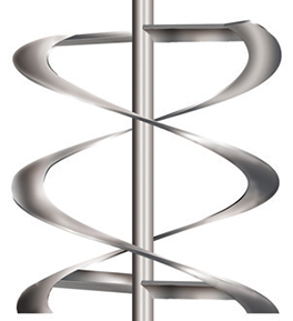
▲Figure 1. A helical ribbon impeller, or helix impeller, can be built with one or more flights, or continuous ribbon sections. This impeller has two flights. Photo courtesy of Chemineer, a brand of NOV.
Although it is possible to mix high-viscosity fluids with simple turbine agitator impellers (if enough are used and at a large enough impeller-to-tank-diameter ratio), if both mixing and heat transfer are required in an agitated vessel, the best choice of impeller is a helical ribbon impeller, i.e., a helix (Figure 1). This is especially true for laminar flow applications, in which helix impellers are typically used.
Helical impellers are often referred to as close-clearance impellers because they are usually applied at an impeller-to-tank-diameter ratio above 0.95, which promotes good heat transfer at the vessel wall. These impellers can be built with one or more flights, or continuous ribbon sections. Figure 1 shows a two-flight design, which will be used as the basis for the calculations presented in this article.
Regardless of impeller type, all of the power drawn by the impeller rotating in liquid is dissipated as heat. For example, if the goal of an application were to heat the vessel contents, the total heat applied to the vessel would be the sum of the heat of agitation and the heat transferred through the vessel walls. In this situation, the net heating rate would continuously increase with increasing agitation. However, heat supplied through the vessel jacket may have a lower cost than the electrical cost of heat provided by the agitator motor.
The most common heat-transfer requirement for viscous liquids is cooling. In cooling mode, the power drawn by the agitator is subtracted from the heat transferred through the vessel walls to determine the net cooling rate of the vessel contents.

Let’s consider the governing equations. Heat transfer through the vessel wall is governed by the generic equation:
where NNu is the Nusselt number, K is a heat-transfer constant, NPr is the Prandtl number, and NRe is the Reynolds number. The constant K depends on impeller type and includes geometric factors such as impeller-to-tank-diameter ratio, pitch, diameter, etc. The geometric factors were omitted in this equation, but expanded forms of this correlation that include these terms may be found in Ref. 1. The value of K is fixed for a given tank and impeller geometry for laminar flow.

The Nusselt Number, NNu, is defined as:
where h is the convective coefficient, T is the tank diameter for a jacketed vessel, and k is the thermal conductivity of the fluid.

The Prandtl number, NPr, is a physical property parameter, defined as:
where CP is the heat capacity at constant pressure and µ is the viscosity.

The Reynolds number, NRe, is a measure of how turbulent or laminar the flow is, and is defined by:
where D is the impeller diameter, N is the shaft speed, and ρ is the liquid density.
In Eq. 1, for a given set of conditions, the contribution of agitation is in the Reynolds number. For a given tank and impeller geometry, the only agitation variable is the shaft speed, N. Since the Reynolds number is to the 1/3 power in the Nusselt number equation, the process-side convective heat-transfer coefficient is proportional to N1/3.

The power, P, of any agitator may be expressed as:
where NP is the power number. For the specific case of laminar flow, the power number can be defined as:
where...
Would you like to access the complete CEP Article?
No problem. You just have to complete the following steps.
You have completed 0 of 2 steps.
-
Log in
You must be logged in to view this content. Log in now.
-
AIChE Membership
You must be an AIChE member to view this article. Join now.
Copyright Permissions
Would you like to reuse content from CEP Magazine? It’s easy to request permission to reuse content. Simply click here to connect instantly to licensing services, where you can choose from a list of options regarding how you would like to reuse the desired content and complete the transaction.