

An increasing share of chemical process industry focus can be described as advanced manufacturing (AM) because of the increasing importance of process intensification, smart manufacturing technologies, and the global need for sustainable processes and chemical products. These changes affect how we should think and teach about AM.
As Ka Ming Ng and I outlined in our article The ChE in Context in Chemical Engineering Progress in October 2017, AM technology is driven by the continuing need to improve chemical product quality; the importance of sustainability, including social responsibility across the supply chain; the need for design methods that produce inherently safer processes and chemical products; the broadening of underlying ChE technology; and, most critically, the increased emphasis on business-to-consumer products in the chemical process industry. Signature elements of AM include:
- The ability to manufacture affordable products that meet human needs in a sustainable manner;
- Deep integration of transport and reaction processes with process design, leading to intensified processes;
- Continued development of advanced sensors/actuators, AI applications, and model-based simulation tools; and
- The emerging ability to co-optimize chemical products, processes, and supply chains.
As the chemical engineering profession evolves, so must the curriculum of the undergraduate degree. As we described in the CEP article, a new intellectual framework is needed for AM processes that builds on the more-traditional set of unit operations. An expanded taxonomy of unit operations – including additive and self-assembled manufacturing processes – will encompass technologies such as 3D printing, process intensification, and nano-scale patterning and assembly processes. Transport processes, reaction kinetics, and interfacial phenomena should be taught in the context of making advanced chemical products. Integrated product and process design will define the capstone AM chemical engineering design experience.
What is not surprising – but does not appear to have been explicitly addressed in the chemical process design education community – is the strong degree of overlap between design method development for chemical products and processes and those methods that exist in the systems engineering discipline.
This article is a closer look at how managing AM innovation can be taught within the undergraduate capstone design experience, specifically emphasizing the integration of chemical product- and process-development lifecycle analysis using model-based systems engineering design languages, methods, and tools. Design languages provide a machine-independent standardized grammar for communicating and displaying design elements and their relationships; examples include the Unified Modeling Language (UML) and the Systems Modeling Language (SysML) [1]. Design methods are the approaches to implementing an engineering project and define the scope of the lifecycle model, its elements, and the order in which the processes are to be carried out; these methods can include Stage-Gate approaches [2,3,4] and innovation maps [3,4] to formalize design activities within the product/process concept exploration, design, and implementation phases of the project lifecycle. The formulation of equation-based frameworks for direct optimization of product properties and manufacturing process design [4,6] also can be considered design methods, as they rely on methodologies for context development and the definition of the appropriate optimization program. Design tools are the actual software implementation of the design languages and methods, including SysML environments or GAMS as a means of implementing the equation-based design methods.
What is not surprising – but does not appear to have been explicitly addressed in the chemical process design education community – is the strong degree of overlap between design method development for chemical products and processes and those methods that exist in the systems engineering discipline.
Consider the project life-cycle model (LCM) depicted below, patterned after the SE vee model depicted in the INCOSE SE Handbook [7]. Comparing the phases of the proposed Vee LCM to those of the Stage-Gate (SG) process, we see that the latter map directly to the former. The concept phase of SG corresponds to the stakeholder and system requirements identification stages of the vee with the system functional review (SFR) acting as the gate review. Feasibility is assessed in the preliminary design phase of the vee with feasible products screened during the preliminary design review (PDR). Development in the SG process corresponds to the detailed design phase with the critical design review (CDR) screening the winning manufacturing options. The manufacturing phase of the SG process is split hierarchically among component, element, and system integration phases of the vee with the requirement verification tests corresponding the manufacturing gate review. Finally, the product introduction phase of the SG process corresponds to the systems acceptance phase of the vee, with product validation serving as the final gate review. We note that an analogous connection between the SE vee LCM and innovation maps also can be formulated.
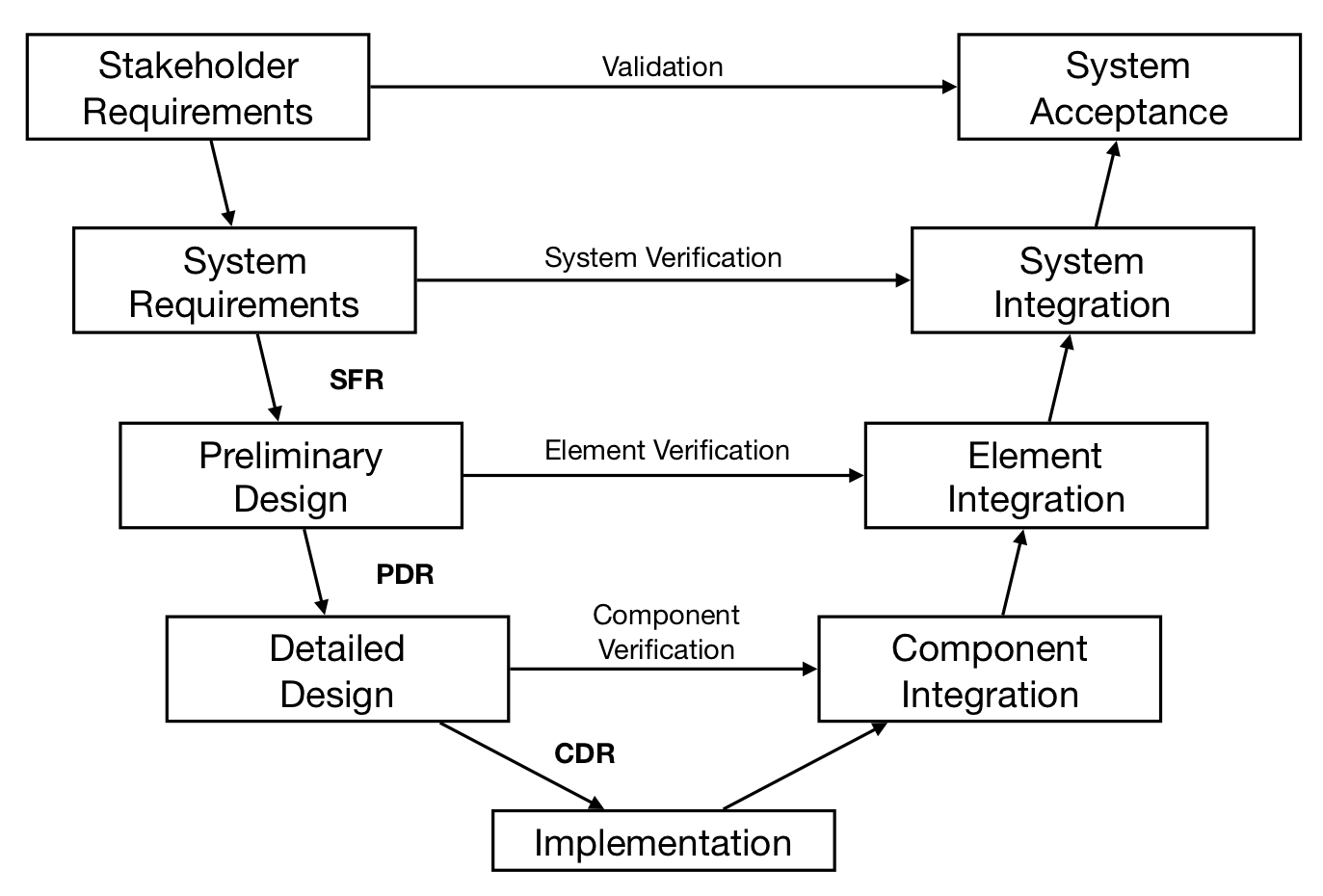 The LCM vee model: Interpreting the SE vee model in the context of a product/process life-cycle model (LCM). The LCM encompasses the design and development phases as well as the verification/validation connections, illustrating the potentially iterative manner of the product/process design process. Gates between the design phases consist of the system functional (SFR), preliminary (PDR), and critical design (CDR) reviews.
It is not entirely surprising that this one-to-one mapping exists; however, what makes it important is that it opens the door to using the wide range of systems engineering methods and tools to continue the formalization of chemical product/process design, particularly in the concept development phase.
Moreover, in terms of the capstone engineering design experience, the LCM vee model provides a useful roadmap for structuring a semester-long product/process design project. Initial design activities should focus on identifying the product and process functional requirements consistent with stakeholder needs. Product and process safety can be addressed early on in terms of stakeholder programmatic requirements. Use-case diagrams can be effectively used to identify chemical product performance requirements. The matrix-algebraic requirements trace and allocation methods (RTM and RAM) can be used to connect requirement relationships through the design decomposition process to guarantee that the stakeholder-level requirements are met. Likewise, verification and ultimate validation of the requirements can be handled in a systematic and rigorous manner.
References
[1] Delligatta, L. SysML Distilled. Addison-Wesley (2014).
[2] Harmsen, J., A. B. de Haan, and P. L. J. Swinkels. Product and Process Design: Driving Innovation. Walter de Gruyter GmbH, Berlin (2018).
[3] Seider, W. D., D. R. Lewin, J. D. Seader, S. Widagdo, R. Gani, and K. M. Ng. Product and Process Design Principles: Synthesis, Analysis, and Evaluation, Fourth Ed. John Wiley & Sons, Inc., New York (2017).
[4] Seider, W. D., S. Widagdo, J. D. Seader, and D. R. Lewin. Perspectives on chemical product and process design. Comput. Chem. Eng. 33 (2009) 930-935.
[5] Cignitti, S., S. S. Mansouri, J. M. Woodley, and J. Abildskov. Systematic optimization-based integrated chemical product-process design framework. Ind. Eng. Chem. Res. 57 (2018) 677-688.
[6] Zhang, L., D. K. Babi, and R. Gani. New vistas in chemical product and process design. Annual Rev. Chem. Biomol. Eng. 7 (2016) 557-582.
[7] Walden, D. D., G. J. Roedler, K. J. Forsberg, R. D. Hamelin, and T. M. Shortell. Systems Engineering Handbook : A Guide for System Life Cycle Processes and Activities, Fourth Ed. International Council on Systems Engineering (INCOSE), John Wiley & Sons, Inc., New York (2015). Figure 3.6.