
Sections
Discrete control is widely used in industry, yet many university-level courses do not cover this type of control.
Process control in the chemical process industries (CPI) is often characterized as a combination of three different types: continuous, batch, and discrete. For decades, process control education for chemical engineers has focused mainly on continuous control and has been further constrained by focusing primarily on continuous linear processes operating at or near steady-state, which is common in some chemical plants (e.g., petrochemical plants). As a result, the typical university process control course has not kept pace with the practice of process control in industry, with little attention paid to batch processes (which are typically non-continuous, nonlinear, and non-steady-state) or discrete control (1, 2).
This article discusses discrete control operations, their importance, application, and related specialized software and equipment. The objective of this article, in combination with a previous CEP article on batch control (2), is to provide graduating chemical engineers with a better idea of what to expect when they arrive in industry regarding the control of industrial processes.
Background
Linear continuous process control, which dominates current undergraduate process control education, focuses mainly on feedback control loops that use a proportional-integral-derivative (PID) control algorithm. PID control is commonly used for temperature, pressure, agitation, and flowrate control of chemical unit operations, where continuously updated analog measurements provide values over a continuous span, and analog valves are controlled over a continuous range. Analysis tools such as Laplace transforms, Bode plots, root locus analysis, and Routh/Nyquist stability algorithms are applicable. These topics, along with PID loop tuning, consume the majority of undergraduate process control class lecture time.
In contrast, many process control applications are nonlinear, non-continuous, and non-steady-state processes involving a sequence of steps (e.g., batch), and almost all processes involve some use of discrete control. Discrete control includes applications for which the inputs and outputs have a limited number of states (usually two but sometimes more), such as on/off, true/false, open/close, or 0/1. A familiar non-chemical system that uses discrete control is the automobile, where automatic gear shifting, windshield wiper operation, deployment of airbags, and generation of alarms and warnings are examples of discrete operations. If the current undergraduate process control course used an automobile as a process/system example, the course would probably concentrate on cruise control, a continuous paradigm for which a PID algorithm could be used, and omit the many examples of discrete control.
An example of discrete control in industry is the machine control of a fill-finish manufacturing assembly line where bottles are filled with product and then capped, labeled, inspected, and packaged. Such processes may utilize numerous limit switches, solenoid valves, timers, relays, and other devices with dual-valued positions or logic with two (or a small number of) possible values. These applications often involve sequential control with interlocks. In addition, Z-transforms are a more suitable analysis tool than Laplace transforms for these applications (e.g., when sampling time is an important variable).
Many of the sensors involved with discrete control are rarely covered in undergraduate process control education. Examples include vision systems (e.g., cameras or other devices that perform pass/fail inspection of manufactured items), optical sensors (e.g., detecting presence or color), encoders, barcode and radio-frequency identification (RFID) devices, and counters/totalizers (e.g., counting the number of shots of acid delivered to a vessel for pH control). Likewise, many common discrete control output devices are not covered in the process control course (e.g., robotic arms, solenoid valves, servo/stepper motors).
Further, discrete control algorithms are usually different than the traditional PID controllers that dominate continuous closed-loop control. For example, statistical control algorithms are often used when inspecting a high frequency (e.g., hundreds/min) of manufactured items. Often, applications use a combination of continuous PID and discrete control (e.g., when linking safety interlocks to conventional control loops).
The most common type of control computer in industry is the programmable logic controller (PLC), which was originally designed to replace mechanical relay control systems with ladder logic software. Note: Early PLCs could only use ladder logic; today’s PLCs have multiple tools available, including ladder logic. The many relay logic replacement applications were (and are) a form of discrete control (3).
As discussed, applications of discrete control are widespread in industry. These applications are especially important in complementing continuous control (e.g., with interlocks, fail-safe logic) and the final steps of many manufacturing processes (i.e., when the product value is at its highest). Discrete control often involves sensors, output devices, programming/configuration languages, and algorithms that differ from those used in conventional continuous analog control loops. To not include this major component of process control in the chemical engineering process control course is a significant omission.
Discrete control: Description and tools
Process applications that typically use discrete control include:
- batch reactors
- process campaign startup, shutdown, and changeover
- material transfer (e.g., pipelines, conveyors, automated guided vehicles)
- material forming (e.g., rolling, molding, drawing, extrusion, web control)
- filling bottles and vials
- vision and inspection
- packaging (e.g., pick and place, box/carton/pallet, labeling barcodes, and RFID)
- assembly (e.g., cars, circuit boards).
Note: Web control refers to the manufacture of “web” items — defined as thin, flexible, and continuous sheet materials such as paper, plastics, films, foils, and metals.
Brief history. Before electronic automation systems became widespread, most discrete operations were controlled by operators, and control devices were selected and installed by electrical engineers. Pushbuttons, switches, and lights mounted on a control panel were used for manual discrete control and were not something that chemical process engineers needed to design or focus on, other than to perhaps develop procedures and train operators during process commissioning.
Today, with widespread plant automation and many functions available via user-configurable software (vs. historical use of hardware), system development is usually performed more cooperatively, with electrical engineers and process engineers working together. For example, the process engineer decides when a pump needs to turn on and off. The control engineer then translates this into control software logic and brings the desired functionality to reality in the control system. In some plants, one person may be responsible for both of these tasks.
With discrete control devices becoming inexpensive, more reliable, increasingly diverse, and compatible with standard industrial control system communication protocols, they are now widespread in chemical manufacturing plants. However, discrete control devices are not alone in this regard. In general, most process control instrumentation has evolved significantly, adding functionality and providing more real-time information than in the past. For example, control valves can now be implemented with highly accurate positioners, and many instruments include multiple sensors, diagnostic information, and compatibility with multiple digital communication protocols.
The discrete control field now includes inputs from position sensors, encoders, vision systems, and identification systems that provide real-time information on “what, where, and how fast” operations are occurring rather than a simple physical property measurement. Similarly, discrete control output devices now include robots, servos, and stepping motors. These are all helping to enable the current wave of advanced manufacturing.
Discrete control equipment. Panel-mounted single-loop controllers were often the basic building block for a control system in the past. Electronic distributed control systems (DCSs) were developed, in part, to reduce the footprint of the control system and enable a single operator to have a much larger span of control. Single-loop controller specification, DCSs, and advanced process control (APC) used to be the domain of control engineers and relay control used to be the domain of electrical engineers. Now, all of these functions can be configured on a single unified platform (consisting of one-to-many integrated computers), which is often smaller, less expensive, more functional, and easier to quickly modify than older systems. Quick changeability of application software is important given the rapidly changing needs of the CPI.
There are significant functional differences between platform components adept at traditional analog control and those designed for specialized discrete control (e.g., multi-axis motion). Scale differences are also an important factor in control systems. For example, a micro PLC that controls a single vessel operates on a much different scale than a DCS capable of controlling an entire plant (3, 4). While a traditional DCS might not be a good fit to control a high-speed filling machine, a modern plant-wide control system might include this capability via a vendor-supplied, skid-mounted system that ties back to the plant-wide system.
An analog control loop and a discrete control sequence must often exist side-by-side and work hand-in-hand. This is true whether the application is, for example, a batch chemical process or a robotic-controlled assembly process.
Languages and the IEC 61131-3 Standard. Historically, DCSs have used function blocks for most control applications, while PLCs have used ladder logic. Released in 1993 and updated multiple times over the years, the current IEC 61131-3 standard sets forth four languages available in control systems: function block diagrams, sequential function charts (SFCs), structured text, and ladder diagrams (5). A previous language in the standard — the instruction list language — was removed in the third edition of the standard. The different languages can be applied across different applications, although some applications have preferred languages. A major benefit of the standard is that it reduces the historical separation between typical continuous and discrete control applications and facilitates the integration of analog and discrete control.
Function block diagrams lend themselves well to traditional dynamic process control. They also work well for Boolean logic, which can be easier to read on function block diagrams than ladder diagrams. Function block diagrams use blocks to represent mathematical and/or logic functions and lines to show data and logic connections. Similar to ladder logic, they are executed periodically by the controller. Because function block diagrams simplify the visualization of complex math and logic functions, the data flow that might exist on many ladder networks can easily be seen on a single sheet of a function block diagram.
An example of a function block diagram is shown in Figure 1. This example involves determining if all of the required conditions exist to permit the turning on of a monomer feed pump (not shown) to a tank sitting on load cells (hence the weight inputs). The necessary conditions monitored provide the 0/1 status of several open/close tank valves (XVs), the tank agitator, and tank level (based on weight measurements). These are sent to a “permissives” block, which provides permission to pursue a process action. If all input states are as desired (i.e., all 1s), the block output will allow the feed pump to turn on.
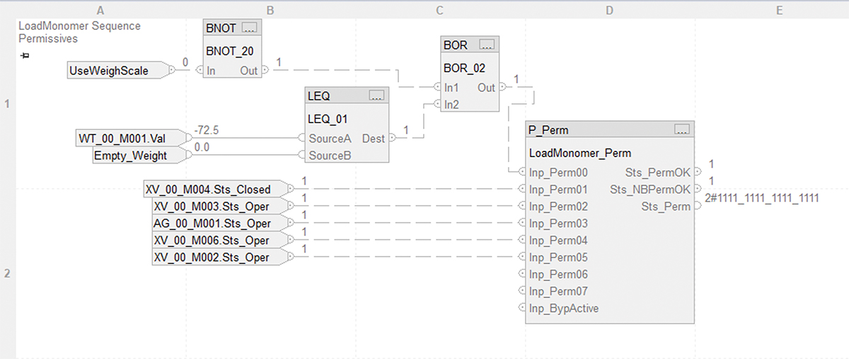
▲Figure 1. Graphical representation of logic helps facilitate application development and support. In this function block diagram, Boolean logic is used to permit the start of a sequence for a monomer feed pump to a tank. If the tank is below a certain weight, the block will permit the feed pump to turn on.
The example includes both simple Boolean logic (NOT, OR) and an analog comparison (LEQ), and incorporates the status of multiple discrete devices. Connection lines depict data flow and block performance logic. The equivalent functionality in ladder logic or most other programming or configuration paradigms would be more difficult for most non-control engineers to visualize and understand.
SFCs, as the name implies, are ideal for the control of sequences. They provide visualization of events proceeding over time or in some logical order. It is easier to visualize the sequential flow of a process using this type of diagram than a structured ladder diagram.
The basic chart building blocks are the step and the transition. The steps of the sequence are executed in a particular order. A step is where an action takes place such as “Turn on Pump-101” or “Reset Totalizer-101,” which are discrete logic operations. Transitions (triggered as a form of discrete control) are typically based on time or a particular logic condition such as temperature exceeding a setpoint. A transition is examined after the step is complete and tests for a particular condition, e.g., “Is TI-102 > 102.1°F.”
Figure 2 shows an example of an SFC that checks the normalized water permeability (NWP) in a filtering process. The rectangles are steps where actions such as setting the flow path take place (labeled as VALVE PATH) and the crosses are transitions where a condition is tested before the sequence can proceed. In the transition at the bottom, NWP_Tran_002, the sequence is looking for the valve path (VP) to have reached the desired state as set in the step above it.
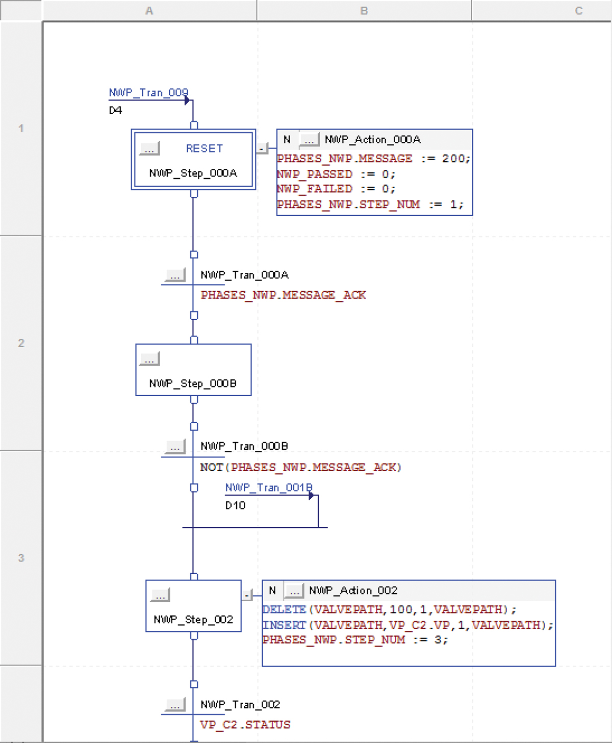
▲Figure 2. This sequential function chart (SFC) shows a portion of the step logic to check the normalized water permeability (NWP) in a filtering process sequence. The rectangles represent actions (e.g., setting the flow path) and the crosses represent transitions where a condition is tested before the sequence can proceed.
An advantage of tools such as SFCs is that they not only provide a visual image of the relevant logic, but they are also the application itself. Sequential logic is realized with no programming or additional software configuration usually needed. That is, the steps and transitions contained in the SFC link directly to relevant input/output field signals that interface to the control computer.
Structured text, based on the PASCAL programming language, can be useful for certain calculations where simple programming might be desirable for a repetitive operation (e.g., FOR-NEXT loop with arrays). For example, a single simple calculation of tank level is fine in a function block diagram, but structured text might be preferable in using the same algorithm to determine the level for a large number of vessels.
Ladder logic, the historical standard for discrete logic, is still common. Its graphical nature can simplify the depiction of Boolean logic. With any of the languages, good program structure, programming technique, and documentation (including detailed commenting) are critical to the use, support, change control, and debugging of the program.
Application areas
Sequential control. The two main application areas of sequential control in the CPI are batch processes and startup/shutdown of continuous processes. Sequences can have branches, loops, and decision points, and these can be based on either measured conditions or input parameters. An example of batch sequence control is the mashing process in beer brewing, where a sequence of discrete operations adds defined amounts of ingredients to the mash and then proceeds through heating and cooling steps before the inoculation step. Bioreactors producing the active ingredient for medicines use a similar sequence and thus make significant use of discrete control.
Batch and startup/shutdown of continuous processes are similar. Both have a defined set of steps that involve measurements, setpoints, and turning on and off devices to create the necessary process conditions.
Machine control. Machine control is a branch of sequential control. Most applications are primarily mechanical (e.g., 3D positioning of output devices). Examples of processes that use machine control — typical in manufacturing lines — include filling, cutting, molding, assembly, and packing.
A machine control system is typically differentiated from process control by motor and motion control. While continuous process control will have motors and variable frequency drives, machines will have servos and steppers where exact positioning is needed. In addition, machine control is typified by large numbers of discrete sensors signaling presence or absence (typically of position, product, or light) to trigger operations. The development of advanced sensors for high-speed measurement of thickness, position, and distance have aided machine development.
Whether for sequential or machine control, the process is typically defined through a state diagram showing all the states, steps, and transition conditions. Examples of states include running, paused, idle, aborted, held, and stopping (as defined by the ANSI/ISA 88 standard).
Robotics and motion control. Robotics in manufacturing is a special branch of machine and motion control. Robots are machines that can execute repetitive mechanical tasks without human intervention. The difference between a robot and machine is that a robot performs a smaller number of operations, is simpler, and is typically flexible (i.e., can be easily reprogrammed to perform many different operations). A robot might perform one operation as part of a machine. For example, a robot might perform a pick and place operation for a machine.
Motion control is another building block for many discrete control operations. Servo and stepper motors are at the heart of machines and robots. They allow precise motions to occur. The components are the controller, motor, and position feedback which can be highly integrated. As a result, high-precision mechanical operations are possible.
Industrial robotic control applications present many unique challenges for automation engineers. One of the challenges is the planning problem, in which the arc of motion must be defined to ensure that a robotic arm gets from a starting point to an ending point without colliding with any obstacles. Path smoothing may also be necessary to avoid abrupt and sharp turns. In addition, industrial robotic applications require capabilities over and above those provided by most DCS and PLC platforms, meaning engineers may have to learn one or more vendor-specific proprietary programming languages or other languages such as C/C++, Java, or Python.
Identification, inspection, and tracking. Discrete control can allow for easy tracking of materials moving around the facility or factory floor. For example, when a bin of materials arrives at a station, it is important that it be verified as the right material. Batch lot tracking is another important application.
Barcode and RFID readers with links to the control system are the base components of identification, inspection, and tracking. Software uses such readers to identify the component part or material, compare it to what was expected, and prevent further operations if it is not correct. Furthermore, some of this information may need to be passed to the manufacturing execution system (MES), warehouse inventory management system (WIMS), and/or enterprise resource planning (ERP) systems. These sensors have evolved to be extremely high speed and work at a distance. A reader can track individual packages on an entire pallet as they leave the warehouse just as it can accurately track the individual times of 50,000 runners in a road race.
Vision systems are often used for component identification and defect detection. They are trained to differentiate between what is desired and what is not and provide signals to a machine to guide the proper operation based on what is seen. An example is label inspection on a bottle. A vision system can identify if the proper label is present and if the label has the key required features. Similarly, a vision system can identify if the proper materials are at a particular station based on size, shape, and/or color. A vision system can also perform counting operations such as counting cells on a microscope slide (to determine cell density from a bioreactor sample).
Some vision systems, such as ones involving cameras, might require data reduction algorithms to reduce the huge amount of real-time data arriving from screen images to a single “discrete” pass/fail indication.
Specialty applications exist. Several special case applications of discrete control exist, such as web control. Web control utilizes special control strategies to keep defined web materials (e.g., sheet metal, paper, plastic films) moving without wrinkles or tearing. Proper torque, tension, and steering are key requirements for such control.
PackML: An industry technical standard for the control of packaging machines. A software standard for discrete process packaging lines, called PackML (Packaging Machine Language), was developed by the Organization for Machine Automation and Control (OMAC) in conjunction with the International Society of Automation (ISA). PackML was introduced in a technical report titled TR 88.00.02-2015, “Machine and Unit States: An implementation example of ANSI/ISA 88.00.01.” The primary objective of PackML is to bring a common “look and feel” and operational consistency to all machines that make up a packaging line (and other types of sequential/batch discrete operations).
Discrete control challenges
Data context. The data from sensors, devices, and machines for discrete control (or any kind of control) is of little use unless it is contextualized. Data needs to be presented in a way so that meaningful trends, patterns, and correlations are possible. This means data needs to be properly labeled. For example, data from a batch process should include a timestamp, equipment identifier, batch lot number, and perhaps batch step identifier. Data validation is often necessary (i.e., identifying and discarding invalid data). Meaningful contextualized data allows manufacturing, technical service, quality control, and management personnel to make good operational decisions. However, challenges in contextualizing data can arise when discrete control data needs to be combined with process data in other databases with different timestamps and data formats.
Cooperative development and vendor-packaged systems. Modern control systems are modular and flexible and lend themselves to cooperative development among vendors, end-users, consultants, and/or contractors. And, integration of vendor-packaged systems to plant-wide control computers, while still sometimes challenging, is simpler than in the past.
Open protocols and standards-based communication exchanges make control systems easier to implement, integrate, and manage. Real-time data exchange is simplified through the use of standard networks and protocols. ODVA, Inc. (formerly Open DeviceNet Vendors Association, Inc.), Profibus, and Profinet International (PI) are international organizations committed to developing standards and products around open standards for industrial system communications.
Challenges often remain if packaged systems (often the home of specialized discrete control applications) must be customized to meet specific customer functional requirements (FRs). For example, packaged systems usually come with their own human machine interface (HMI) and alarm system. However, plant operators typically do not want to deal with different HMIs, alarm systems, and data display formats as provided by different vendors. They will be more comfortable and perform better with a single HMI and alarm system for the whole plant. This utopic vision is not yet easy to achieve.
In addition, many packaged system vendors consider their software proprietary and are unwilling to support customization, as it requires new versions of software they need to support, and warranties may become invalid. Some third-party systems may not be compliant with regulatory requirements for certain applications.
Project management. Management of projects that use discrete process control should follow well-known published project management best practices, including those of particular importance to automation systems (6, 7). Some projects will require compliance to regulations such as the U.S. Food and Drug Administration (FDA)’s current good manufacturing practices (cGMPs) and parts of U.S. Occupational Safety and Health Administration (OSHA) 1910. In general, automation projects should be managed such that the resulting system(s) reliably and consistently meets functional requirements and can be expected to continue doing so in the future.
Regulations and Standards
The process of specifying, designing, implementing, and operating process control systems involves many well-publicized best practices, some of which are requirements for certain or all industries. These include:
- National Fire Protection Agency (NFPA) 70 and National Electric Code, the benchmark for safe electrical design, installation, and inspection
- current good manufacturing practices (cGMPs) set by the U.S. Food and Drug Administration (FDA) for the pharmaceutical and medical device industries
- standards set by the American National Standards Institute (ANSI) and some also set by the International Electrotechnical Commission (IEC), such as the standards for safety instrumented systems (ANSI/IAS-84; IEC 61508, 61511, and 62061), alarm management (ANSI/ISA-18.2 and IEC 62682), batch process control (ANSI/ISA-88), human machine interfaces (ISA-101), and procedural automation (ISA-106)
- requirements promulgated by the U.S. Occupational Safety and Health Administration (OSHA) and U.S. Environmental Protection Agency (EPA)
- ISA 99 and IEC 62443 for cybersecurity
- local building codes
- IEC 61131-3 Programmable Controllers – Part 3: Programming languages
- PackML; TR 88.00.02-2015 (Control of packaging machines).
Note: Robots and vision systems have not yet evolved sufficiently to have their own set of standards.
In Closing
Chemical engineering graduates who start their first process engineering jobs in industry can be expected to serve on teams that generate functional requirements for the control of new plants or retrofits to existing plants. These engineers will subsequently have a role in identifying, developing, implementing, and/or supporting the control systems to meet those functional requirements. The majority of such projects will involve significant use of discrete control. Discrete control is critical to the control of specific portions of both continuous and batch processes, so it is important for engineers to have some understanding of the hardware, software, characteristics, nuances, and challenges involved with such control. Because this topic is not included in most university process control courses (8), engineers will need to learn about discrete control in other ways. This article aims to provide a starting point.
Literature Cited
- Alford, J., and T. Edgar, “Preparing Chemical Engineering Students for Industry,” Chemical Engineering Progress, 113 (11), pp. 25–28 (Nov. 2017).
- Alford, J., and G. Buckbee, “Industrial Process Control Systems: A New Approach to Education,” Chemical Engineering Progress, 116 (12), pp. 35–42 (Dec. 2020).
- Mehta, B. R., and Y. J. Reddy, “Industrial Process Automation Systems Design and Implementation,” Amsterdam, The Netherlands (2015).
- Sharma, K. L. S, “Overview of Industrial Process Automation,” Elsevier, Amsterdam, The Netherlands (2011).
- International Electrotechnical Commission, “Programmable Controllers – Part 3: Programming Languages,” IEC 61131 (2013).
- Sands, N., and I. Verhappen (Eds.), “A Guide to the Automation Body of Knowledge,” ISA, Research Triangle Park, NC (2018).
- International Society of Pharmaceutical Engineering, “Good Automation Manufacturing Practices – Guide for Validation of Automated Systems,” ISPE (2008).
- Samad, T., et al., “Industry Engagement With Control Research: Perspective and Messages,” Annual Reviews in Control, 49, pp. 1–14 (2020).

Copyright Permissions
Would you like to reuse content from CEP Magazine? It’s easy to request permission to reuse content. Simply click here to connect instantly to licensing services, where you can choose from a list of options regarding how you would like to reuse the desired content and complete the transaction.