
Sections
Identify and mitigate stagnant areas in an ethylene plant to prevent polymer buildup that hinders plant performance, reliability, and safety.
Stagnant areas, low-flow areas, and dead legs in an ethylene plant are places where polymer can form and accumulate. Polymer buildup contributes to plant upsets, reduced or no-flow situations, equipment damage and rupture, and in some cases, chemical releases (1, 2). This article discusses how to identify and mitigate stagnant areas in distillation towers and associated equipment. These same steps can be applied to any part of an ethylene plant where stagnant areas and reactive monomers exist.
The terms stagnant areas, low-flow areas, and/or dead legs are used interchangeably throughout this article to avoid repetition. However, these terms are each somewhat different:
- stagnant areas: spaces exposed to vapors with little or no movement
- low-flow areas: spaces exposed to vapors or liquids where there is some movement, but it is slow
- dead legs: spaces where liquid or vapor can get trapped inside a pipe with no movement.
The audit
One of the first steps in an audit of an ethylene plant is to look at the piping and instrumentation diagrams (P&IDs). The goal of the P&ID review is to identify potential stagnant areas on paper before the field audit. For example, a reflux drum has many areas of possible concern (Figure 1). Note that Figure 1 is a simplified diagram of a reflux drum — actual P&IDs at the plant are far more complicated and difficult to review.
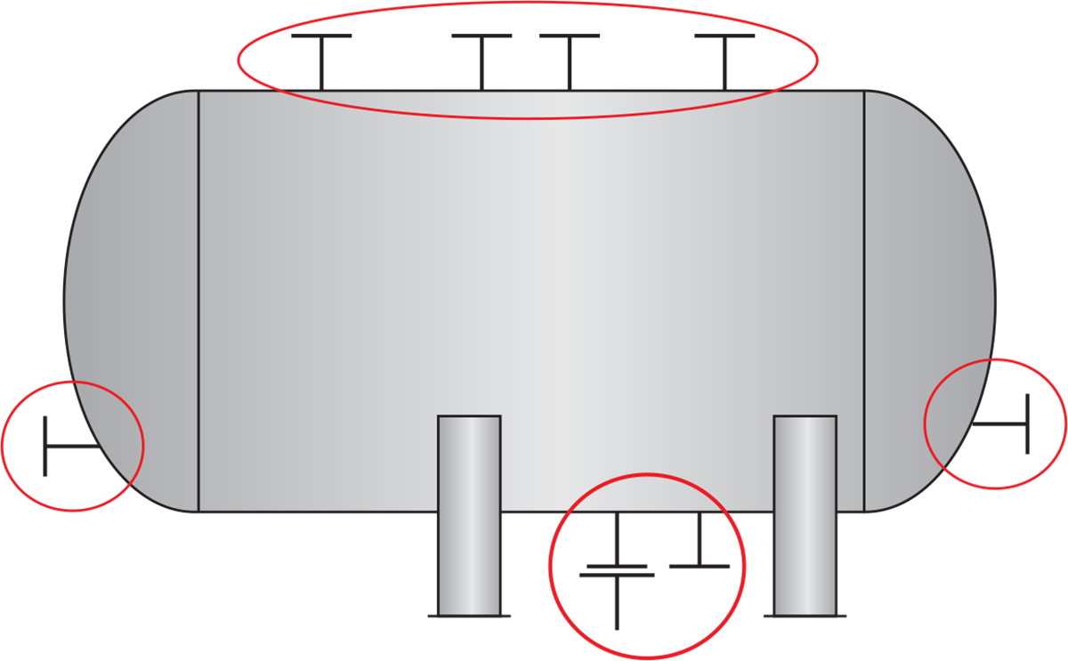
▲Figure 1. A reflux drum has multiple locations for possible stagnant areas.
When surveying multiple pieces of equipment, break the survey into smaller segments to ensure a comprehensive review. Often, stagnant areas are hidden in plain sight, so the auditing team must be meticulous in the survey.
Once the P&IDs have been reviewed, walking the unit is the best way to assess the equipment for stagnant areas and dead legs. Equipment cannot be surveyed completely from an office or the ground. The auditing team will need to climb up to the condensers and reflux drum decks. While in the unit, look for:
- unused taps
- instrument analyzer lines
- rarely used lines (e.g., startup or blowdown lines)
- level bridles
- deep manways
- low-flow areas of exchangers
- relief valve standpipes
- areas where polytetrafluoroethylene (PTFE) has been used for gaskets and seals
- sources of oxygen, which can collect in low-flow areas and increase fouling.
During the inspection, pay close attention to the various heat exchanger designs. Exchangers with large heads may have low-flow areas where polymer can develop. And, most horizontal reboilers in high-fouling services have stagnant areas in the vapor spaces where monomer can condense and polymerize. Figure 2 shows polymer growth in an overhead condenser with a deep channel head.
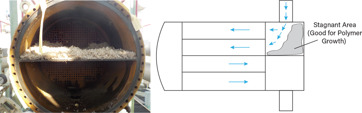
▲Figure 2. Polymer growth may occur in overhead condensers with deep channel heads.
Another part of the survey should focus on the distillation towers. In particular, deep manways in towers are often overlooked. Figure 3 shows several examples of manways with polymer growing in stagnant areas. Typically, polymer in manways is of little concern. In some cases, however, the polymer can initiate further polymer formation or fall into the tower, potentially blocking downcomers or valves. The survey should address any areas that have potential to create further problems.
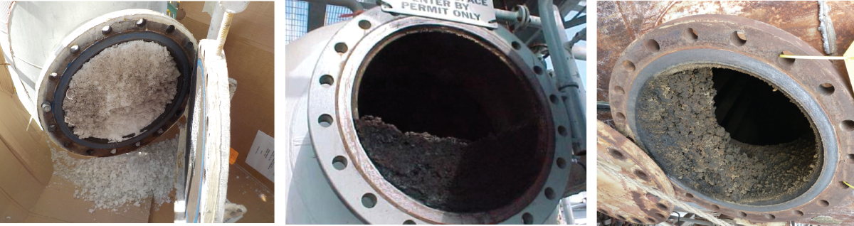
▲Figure 3. Deep manways are often overlooked stagnant areas where polymer can form.
The goal of the survey is to find all of the stagnant areas in the process unit. For example, decanters, exchangers, reflux drums, relief valve standpipes, level gauges, and rarely used lines are all stagnant areas where polymer can grow.
Figure 4 shows some common low-flow areas. Figure 4a is a plugged level bridle (i.e., a vertical pipe connected to the side of a storage tank or process vessel in which the level instrumentation for that vessel is mounted). Figure 4b is a relief valve standpipe where the relief valve has been removed. Figure 4c shows a reboiler design where the reboiler line is “valved off” — a stagnant area exists in this piping when both valves are closed and the reboiler is offline. If the reboiler is offline for an extended period, the valves may leak and allow liquid and vapors to invade the stagnant space. The monomers may then polymerize and foul the reboiler when it is placed back in service. A drain line is needed to remove the liquid, and the space should be purged with an inert gas (e.g., nitrogen) prior to bringing the reboiler back online.
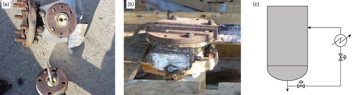
▲Figure 4. Some examples of low-flow areas include (a) a level bridle, (b) a relief valve standpipe, and (c) a valved-off reboiler.
Review the fouling history
As part of the survey, review the equipment’s fouling history. In one example, a plant reboiler had historically long run lengths of about two years. However, it began to experience very short run lengths, eventually running only a few days before having to be taken out of service. Upon inspection, the tubes were clean but the tube sheet appeared to be fouling (Figure 5a). The fouling polymer was chemically identical to previous polymers, but the texture suggested that the polymer was growing in a stagnant area, as the polymer appeared bumpy on one side and smooth on the other (Figure 5b) (3).
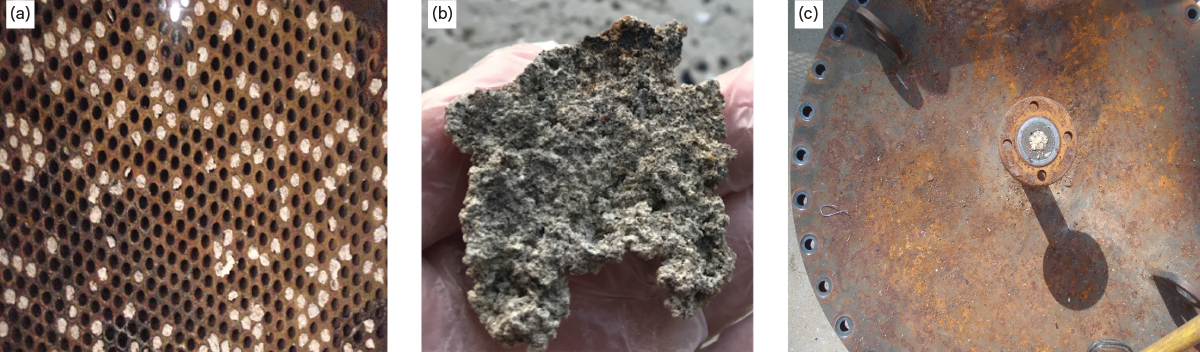
▲Figure 5. A plant reboiler was experiencing much shorter run lengths than usual. Upon inspection, (a) the tube sheets were found to be plugged with (b) a polymer that had a different texture than previous polymers, which suggested the polymer was growing in a stagnant area. (c) The foulant also plugged the tower drain line.
The different polymer texture prompted operators to check the relief valve standpipes on the reboiler. The relief valve vent lines were found to be completely plugged. Polymer was falling from the relief valve line into the reboiler return line and sump of the tower and plugging the reboilers. Unfortunately, this polymer also plugged the tower drain line (Figure 5c), so the only way to remove the foulant was through the reboiler. Even after cleaning the vent lines, the reboiler run lengths only marginally improved. The plant eventually took advantage of another outage to open the tower and clean the sump.
Another contributing factor to the relief valve vent line fouling was the distance from the reboiler to the relief valves. The relief valves for the fractionation section were located in a central location on an elevated deck. This simplified maintenance activities, but caused the piping from the reboilers to the relief valves to be more than 150 ft long with up to eight elbows and transitions from vertical to horizontal sections. The piping internal diameter was between 8 in. and 10 in. Such a long vent line provided plenty of stagnant area for polymer growth, and gravity caused the foulant to fall into the reboiler.
Another contributing factor to polymer formation in stagnant areas is oxygen ingress. Oxygen can collect in the same stagnant areas as the reactive monomers, increasing the probability of foulant formation. In general, assume that a recycle stream from a refinery or polymer plant, or feedstock from a ship or a truck, will have some oxygen that needs to be taken into account. Maintenance activities such as reboiler cleaning may also contribute oxygen to the system.
Identify low- or no-flow areas in your plant
Once the survey has been completed, create a plan to control or eliminate the stagnant areas. The risk assessment should determine the potential for hazard as well as occurrence. Table 1 shows an example risk assessment. Once this is done, create a plan to control or eliminate the stagnant areas.
| Table 1. After surveying equipment, perform a risk assessment to evaluate the stagnant areas and create a plan to mitigate or eliminate the risks. | |||
| Do we have any of the following low-flow or stagnant lines? | Yes | No | What can we do to mitigate the risk? |
| Unused lines | |||
| Dead legs | |||
| Instrument or analyzer lines | |||
| Startup lines | |||
| Blowdown lines | |||
| Level bridles | |||
| Deep manways | |||
| Low-flow areas in exchangers | |||
| Pressure-reducing valve standpipes | |||
| Do we have possible oxygen sources? | Yes | No | What can we do to mitigate the risk? |
| Import streams from off-site | |||
| Recycle streams that could contain oxygenates | |||
| Procedures that could allow oxygen/air in during equipment swaps | |||
| Potential for cooling water leak | |||
| PTFE gaskets or seals in process equipment | |||
| Do we have higher severity now than before? | Yes | No | What can we do to mitigate the risk? |
| Higher percent monomer | |||
| Higher temperatures | |||
| Increased risk of oxygen | |||
| Shorter run lengths due to fouling | |||
| More fouling than in the past | |||
| Lighter colored fouling (white or off-white) | |||
Several diagnostic tools are available to study stagnant areas in a unit, such as borescopes, thermal scanners, X-ray systems, and neutron backscattering spectrometers. Use a borescope when polymer is suspected in long piping runs (Figure 6). When there are several twists and turns, the borescope may not be able to handle that many directional changes. A foam line pig can be used in some longer, multidirectional lines to ensure the line is clean.
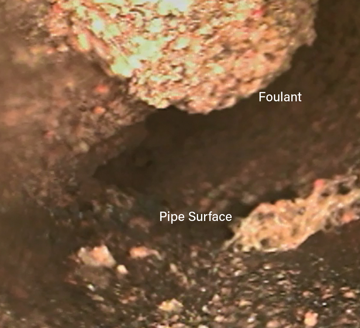
▲Figure 6. A borescope is a useful tool for diagnosing fouling in long piping runs.
Thermal scans can be used to determine if a line is cold when it should be warm, indicating a dead leg. Neutron backscatter can detect blockage in a line and determine the extent of the blockage. In addition, X-ray can be used to determine if a line is partially or totally blocked (Figure 7). In Figure 7, the lighter areas are blocked with foulant, and the darker areas indicate liquid flow.
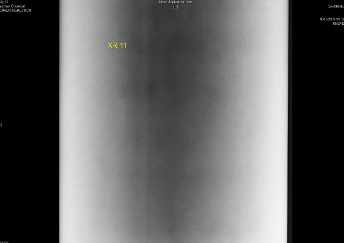
▲Figure 7. In a piping X-ray scan, lighter areas indicate blockage and darker areas indicate liquid flow.
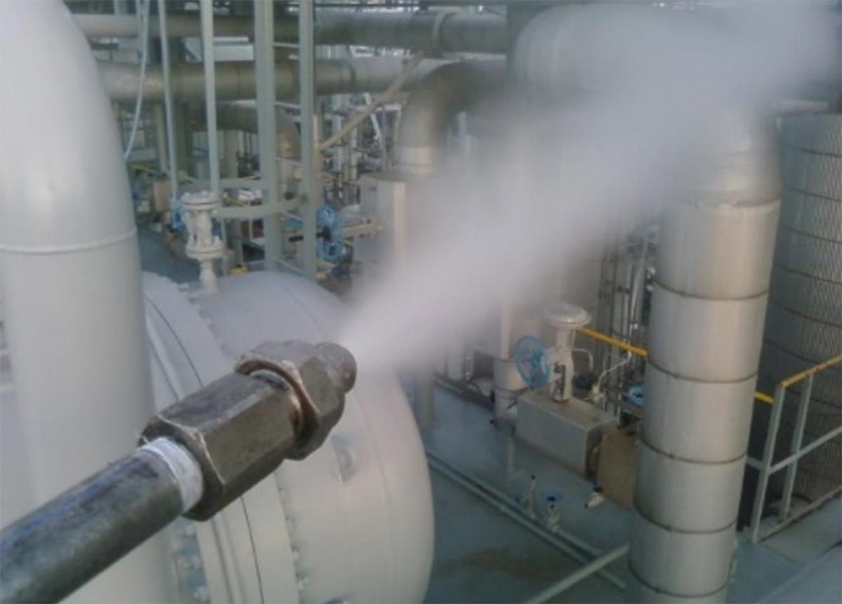
Relief valve lines that are prone to plugging can be treated with a slipstream spray (with or without inhibitor) or flushed with inerts such as natural gas, nitrogen, etc. to help eliminate stagnant areas (Figure 8). An aerosolizing quill is recommended if a liquid is used in the slipstream (Figure 9). For relief valves that are positioned at the end of long piping runs, installing a rupture disc upstream of a long piping run can also help eliminate stagnant areas (Figure 10). This should be considered a best practice for relief valves on long piping.
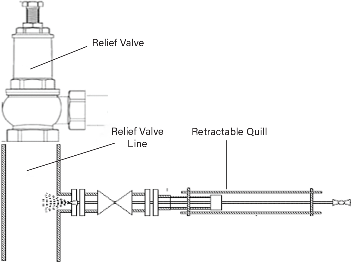
▲Figure 8. Add a slipstream spray to relief valve lines that are prone to clogging to eliminate stagnant areas.
▲Figure 9. Use an aerosolizing spray quill for liquids in slipstreams.
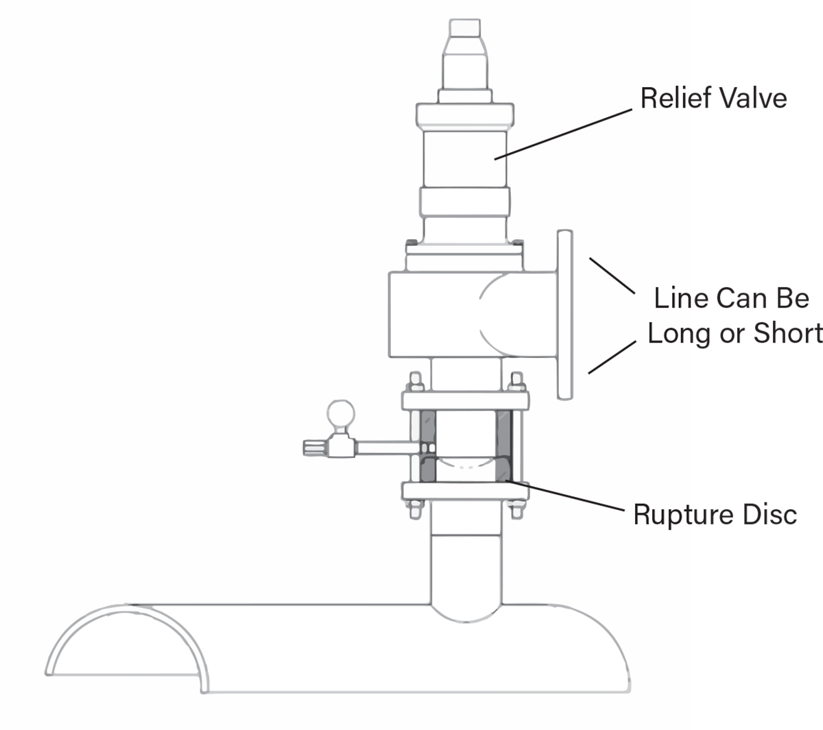
▲Figure 10. A rupture disc on a relief valve vent line in long piping can eliminate stagnant areas.
The rupture disc is positioned near the equipment and opens at a set pressure that is slightly lower than the relief valve (4). Before the disc ruptures, the line between the equipment and relief valve is clear and free of reactive monomer and oxygen, essentially eliminating the stagnant area. After the disc ruptures (Figure 11), it should be assumed the line contains vapors that can polymerize.
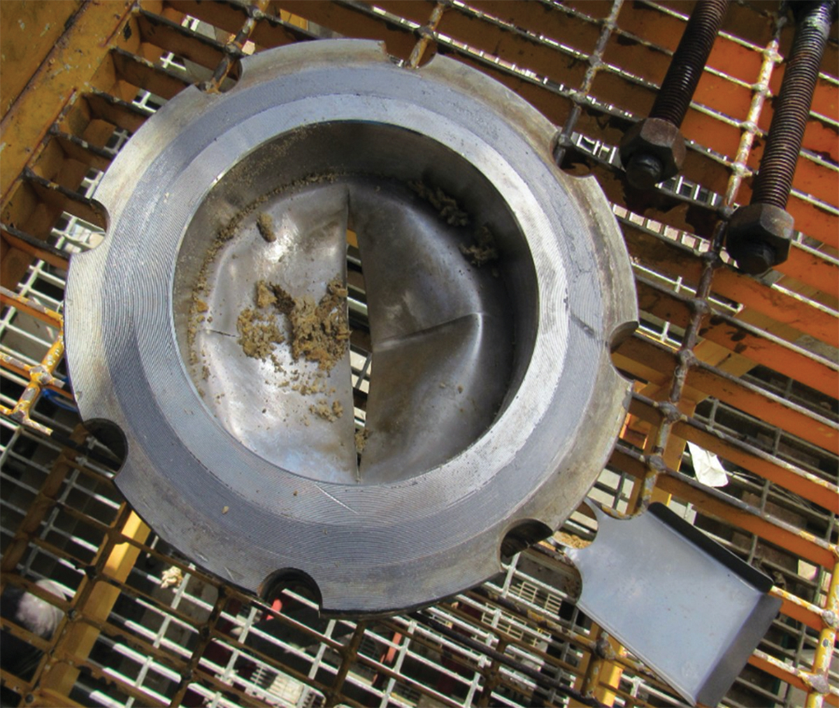
▲Figure 11. If a rupture disc is ruptured, the line most likely contains vapors that can polymerize.
For towers where polymer has accumulated in the manways (Figure 3) and the accumulation is causing a problem or has the potential to cause a problem in the future, some facilities modify the external manways with a spray nozzle and aerosolizing quill during a turnaround to increase flow in the area (Figure 12). In many cases, the aerosolizing quill will require a diluent stream to function properly, such as the bottom stream, reflux stream, etc. The objective is to keep the vapors that collect in those manways moving.
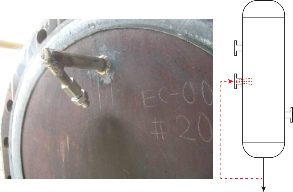
▲Figure 12. Add a spray nozzle to reduce stagnant areas in external manways that are prone to clogging.
Similar to the stagnant manway scenario, condensers with deep heads can create a stagnant area. In this case, the dollar plate can be outfitted with a spray nozzle during a turnaround (Figure 13). If an inhibitor is used for fouling control, the typical injection point is in the condenser feed. If a deep condenser head is creating a stagnant area, the injection point may need to be moved to the condenser endplate, or both injection points (condenser feed and endplate) may need to be used.

▲Figure 13. In condensers with deep heads, relocate the slipstream injection point to mitigate stagnant areas and reduce fouling.
If the inspection reveals unused taps, remove the taps if possible. As with any equipment modifications, ensure that the design ratings are maintained.
Closing thoughts
Polymer can grow in stagnant areas, causing equipment overpressure and/or damage. In a plant survey, looking specifically for all the potential stagnant or low-flow regions will turn up more areas than expected. Once identified, perform a risk assessment to mitigate the impact that fouling may cause. Identifying and mitigating stagnant areas can noticeably improve plant reliability and reduce process upsets.
Literature Cited
- Cheng-Guajardo, C., et al., “Popcorn Polymer Fouling in a Depropanizer Tower System,” presented at the 2020 AIChE Spring Meeting, Paper 189g, virtual (Aug. 20, 2020).
- Coleman, S., and A. Baumgartner, “Myths and Mysteries in the Manufacture of Ethylene,” presented at the 2008 AIChE Spring Meeting, Paper 220d, New Orleans, LA (Apr. 10, 2008).
- Rossana, D., et al., “Visual Clues Give Insight into Ethylene Service Fouling,” Chemical Engineering Progress, 116 (5), pp. 63–69 (May 2020).
- Bours, R., “Use of Rupture Discs in Combination with Relief Valves,” Fike White Paper, https://www.fike.com/wp-content/uploads/2019/02/IPGWP-003-RD-Combo-With-Relief-Valves.pdf (2013).
This article is based on a presentation given at the 2021 AIChE Spring Meeting and Global Congress on Process Safety, April 18–22, 2021.

Copyright Permissions
Would you like to reuse content from CEP Magazine? It’s easy to request permission to reuse content. Simply click here to connect instantly to licensing services, where you can choose from a list of options regarding how you would like to reuse the desired content and complete the transaction.