
An advanced process control (APC) application is only as good as its weakest link. Ensure its stability from the ground up by building a solid foundation.
Advanced process control (APC) encompasses a wide range of process control strategies, technologies, and layers. This article focuses on high-level applications, such as multivariable control (MVC) and model predictive control (MPC), that are designed to control and optimize industrial processes with multiple objectives and constraints.
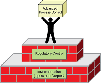
▲Figure 1. To be successful, an APC application must be supported by a solid foundation built of a reliable, well-maintained instrumentation layer and a robust, responsive regulatory control layer.
While many organizational, technical, and human factors can affect the success of an APC application, a solid foundation of instrumentation and regulatory control is critical (Figure 1). The importance of this foundation is typically overlooked and almost always underappreciated. APC is often considered as a distinct, independent control layer that is managed separately from regulatory control and instrumentation, which further degrades continuity.
It is worth spending a little more time and effort on the basics to ensure an APC application that is easier to implement, use, and maintain, and that performs well and delivers benefits in the long term. This article offers some practical tips, recommendations, and troubleshooting techniques to help build a solid foundation for a successful APC application.
Instrumentation — more than just inputs and outputs
Process instrumentation is the backbone of the entire control system. Almost every regulatory control loop relies on at least one measurement (i.e., input) and at least one final control element (i.e., output). The performance of a single APC application may depend on dozens, or even hundreds, of individual inputs and outputs.
Temperature and pressure measurements. Temperature instrumentation, such as thermocouples and resistance temperature detectors (RTDs), are the most basic and common instruments found in industrial plants. While thermocouples are an economical option, RTDs are usually more accurate and offer better resolution. Temperature transmitters should be used whenever possible in control applications. Incorrectly installed, fouled, or damaged thermowells (i.e., tubular fittings that protect temperature sensors) are common sources of temperature measurement problems.
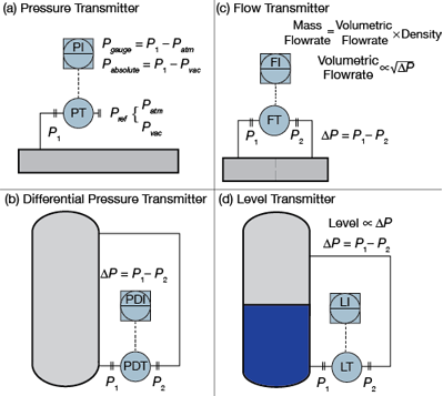
▲Figure 2. The differential pressure (DP) measured between the upstream and downstream ports of a DP transmitter can be used to calculate or infer several process measurements: (a) pressure, relative to a reference pressure; (b) DP between two process connections; (c) flowrate of material (with a known molecular weight or specific gravity) through a flow restriction in a pipe; and (d) level of material (with a known density) in a vessel.
Pressure transmitters are another common and versatile process instrument (Figure 2a and 2b). They typically measure the differential pressure (DP) between one process connection and a reference pressure (atmosphere, Patm, or vacuum, Pvac) or another process connection. DP transmitters are commonly used to infer other process variables, such as flow and level, based on fundamental engineering relationships.
Plugging, fouling, hydration, and/or phase change in the instrument tubing are the most common sources of inaccurate pressure and DP readings. These problems are usually related to improper tubing design/installation (e.g., length, bends, crimps) or insufficient heating or insulation. Intermittent condensing and flashing in the tubing can produce significant noise in DP-based measurements.
Flow measurements. Accurate flow measurements are essential to many regulatory control and APC applications. The most common types of flow transmitters calculate the process flow from a measurement of the DP across a flow restriction, such as an orifice plate (Figure 2c). Volumetric flow can be calculated from the velocity, which is proportional to the square root of the DP, and the geometry of the flow restriction. Mass flow can also be calculated from the density of the material, usually a constant value that is based on design conditions.
Changes in process conditions are the primary source of inaccurate flow measurements. The accuracy of the flow measurement can be improved by comparing measured process conditions to the design conditions. Any measurements used for flow compensation should be sufficiently reliable and representative of the process conditions where the flow is measured. The problem can sometimes be even more fundamental, such as inconsistent orifice calculations and transmitter settings, improperly installed orifice plates, or a missing (or double) square root in the calculation. These mistakes are rare, but they do happen and can be difficult to find and fix.
Level measurements. The level (or height) of material in a vessel can be measured directly in some cases, but DP transmitters are commonly used to infer level as a function of hydrostatic pressure (head) and the density of the material (Figure 2d). The hydrostatic pressure is measured as the DP between the liquid at the bottom of the vessel and the vapor space above the liquid in closed vessels or atmospheric pressure for open vessels. Some level measurements may need to be linearized to better represent the volume of material, depending on the vessel geometry and measured level span.
Calibration error is the main cause of inaccurate level measurements. Level transmitters are calibrated to reflect the relationship between DP and level based on a constant material composition (density). If the composition of the material in the vessel changes significantly, the slope of the calibration will be different. The calibration zero, which is a correction factor used to adjust the measurement offset/bias with no DP (i.e., the vessel is empty), can also cause problems. Figure 3 illustrates how an incorrectly calibrated level measurement may saturate (i.e., flatline) at a low value of 20% even though the actual level is still falling (Figure 3a) or at a high value of 80% even though it is still rising (Figure 3b).
Would you like to access the complete CEP Article?
No problem. You just have to complete the following steps.
You have completed 0 of 2 steps.
-
Log in
You must be logged in to view this content. Log in now.
-
AIChE Membership
You must be an AIChE member to view this article. Join now.
Copyright Permissions
Would you like to reuse content from CEP Magazine? It’s easy to request permission to reuse content. Simply click here to connect instantly to licensing services, where you can choose from a list of options regarding how you would like to reuse the desired content and complete the transaction.